Header Graphic
HISTORY 3 PAGE...

After testing 001, a number of problems serviced.  Experimental work continued with 002 and 003 but the incremental improvement was not enough.  It was clear that case rigidity was an issue.  Also getting porosity free castings necessary for the pressurized oil passages proved challenging.  A complete redesign was done for 004.

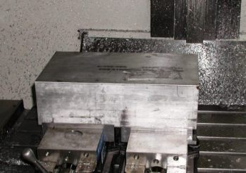
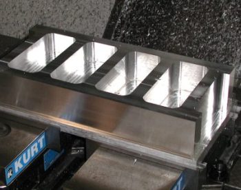
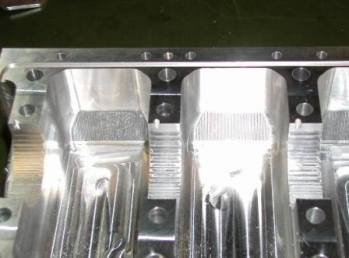
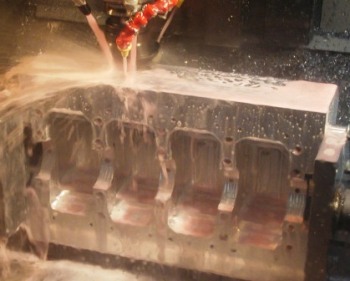
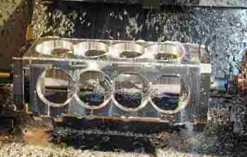
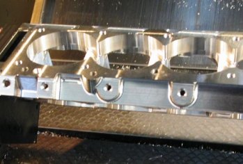
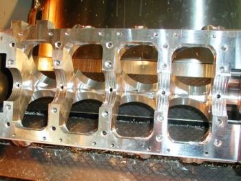
The 004 crank case was cut from solid 6061-T6 aluminum billet.  The case was split at the crank centerline so the caps could be made one piece.  The caps were designed to more than double the stiffness of the top case. A separate sump was retained in the redesign so to be maintenance friendly.

This view shows the caps about 60% machined.  Rough bore, side profile and bolt holes are yet to be done.

For a billet case you start with a block as shown above and mill away everything that doesn't look like an engine.  You are left with about 20% engine case and 80% chips.  It sounds like the hard way to get there but there are advantages.  Besides not having any voids caused by gasses escaping during the casting process, you end up with a product that is dimensionally accurate on all surfaces and 6061-T6 has a 30% higher yield strength than the 356 or LM 25 aluminum casting alloys. The only disadvantage is the higher cost.


This is a close up view of the one piece cap.  You can see the o-ring groove, 10, 8 and 6 mm bolt holes and the profiled bore and case side.  The 8mm hole uses an precision 11mm hollow pin to align the two halves, 10 total.

This is a picture of the topside of the case.  It is being machined on a 4 axis machine.  A bit more material needs to be removed from the sides. 

Top case is near complete.  Lots of chips.

The top case shown spun around on the 4th axis.  And below is the profiled side view of the top case.

   Continue to History Page 4...